
Call 1 (425) 406-1174 to start a Data Recovery!
Hard Drive Repairs
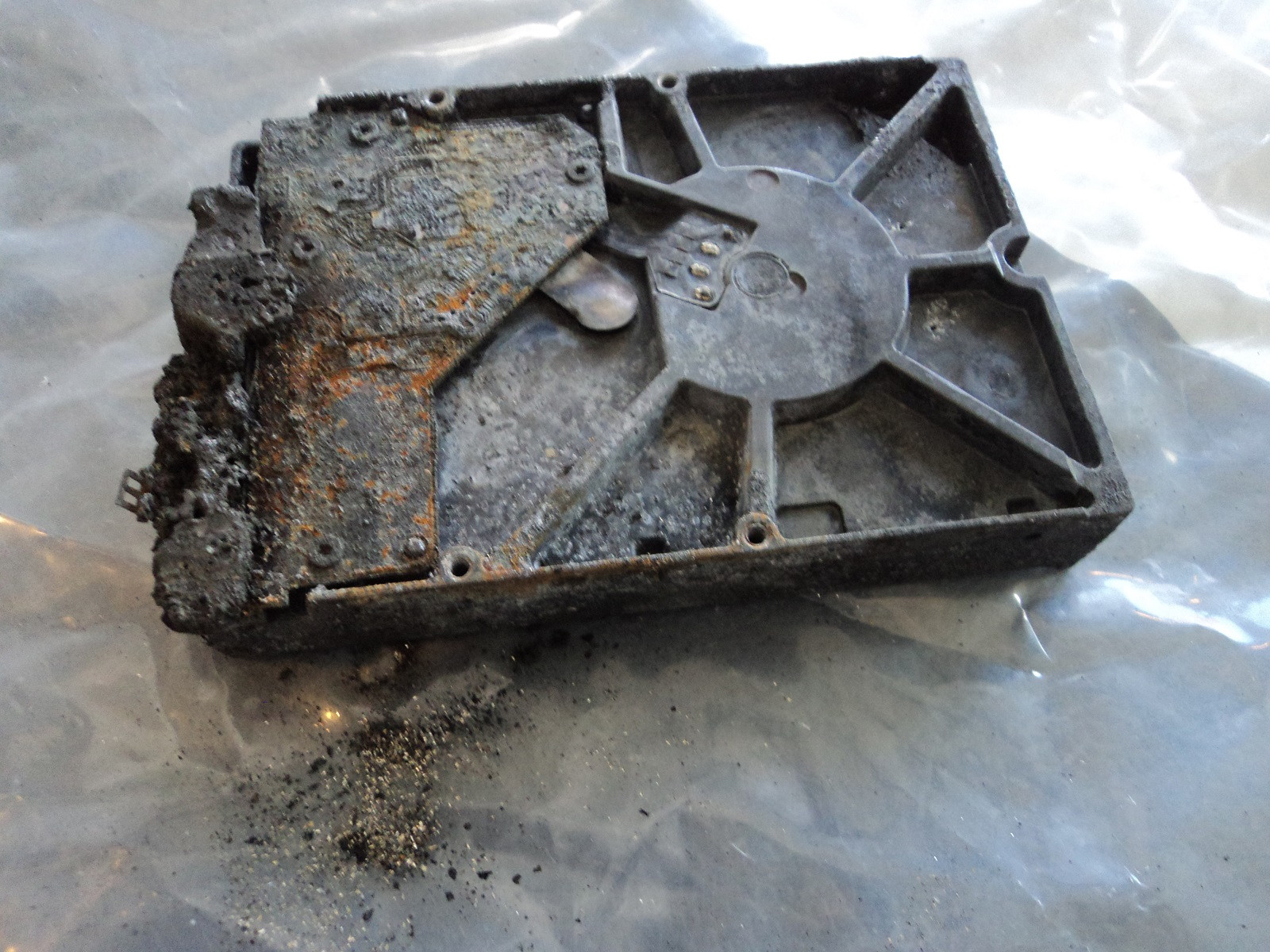
Hardware-Level Hard Drive Repair for All Brands by Seattle Data Recovery
At Seattle Data Recovery, we distinguish between basic data recovery and true hardware-level hard drive repair. When a storage device experiences a mechanical or electronic failure, running recovery software is completely useless—and highly dangerous. The drive must first be physically repaired inside a controlled environment so that it can stabilize long enough to safely extract its data.
Our dedicated laboratory is fully equipped with advanced micro-soldering stations, proprietary firmware terminal tools, and an ISO-certified cleanroom environment. This advanced infrastructure allows our engineers to perform component-level diagnostics and physical restoration across all major hard drive manufacturing brands.
Universal Failure Tiers & Brand-Specific Engineering Protocols
While all hard drives utilize magnetic platters to store data, individual manufacturers rely on wildly different firmware logic, mechanical tolerances, and internal architectures.
Our laboratory engineers deploy specific, brand-calibrated repair procedures to target these unique engineering behaviors:
Western Digital (WD): Bypassing Integrated USB & Encryption
- The Hardware Hurdle: Most portable WD drives (like the My Passport series) do not feature a standard SATA connector. Instead, the USB port and a hardware encryption chip are soldered directly to the main Printed Circuit Board (PCB).
- Our Repair Protocol: If the board suffers a short circuit or the USB port breaks, our technicians perform precision micro-soldering. Under magnification, we tap directly into the drive’s core SATA transmission lines on the board, routing them out to our diagnostic hardware while keeping the encryption chip active to prevent data scrambling.
Seagate: Resolving Seized Spindles & Firmware Loops
- The Hardware Hurdle: Seagate drives feature a compact mechanical design that makes them prone to a "seized spindle motor" or stuck heads if dropped. Additionally, their Media Cache architecture can get trapped in a permanent firmware lock loop when it hits corrupted data sectors.
- Our Repair Protocol: For stuck components, the drive is moved to our dust-free cleanroom where engineers use specialized mechanical tools to safely unstick the head assembly or cleanly migrate the platters to a matching donor chassis. For firmware loops, we link directly to the drive’s system terminal to patch its internal code via RAM commands.
Toshiba: Clearing G-Sensor Lockouts
- The Hardware Hurdle: Toshiba external lines (Canvio series) feature built-in hardware accelerometers (G-Sensors) designed to instantly lock the drive if motion is detected. A sudden drop can trap the drive in a defensive, non-responsive firmware loop.
- Our Repair Protocol: Much like WD, modern Toshiba portable drives utilize integrated USB boards. We convert the native board to a raw SATA path, allowing us to transmit low-level commands that clear out the persistent error logs trapped in the drive’s system memory, stabilizing the controller for data mirroring.
HGST / SanDisk Professional: Enterprise Multi-Platter Alignment
- The Hardware Hurdle: HGST and G-Technology drives spin at higher RPMs (7200 RPM) and often feature tight, multi-platter stacks. They use highly unique NVRAM chips on their PCBs containing custom adaptive alignment data for that specific drive's internal read/write heads.
- Our Repair Protocol: If the PCB fails due to power surges, a simple board swap will fail. Our technicians desolder the original microscopic NVRAM chip and cleanly transplant it onto a perfectly matched donor PCB. Mechanical repairs are performed with absolute precision to maintain the alignment of the multi-platter stack.
The Seattle Data Recovery Hardware Repair Process
Every physically damaged hard drive checked into our lab goes through a strict, controlled restoration pipeline:
- The Cleanroom Inquest: If a drive is clicking, grinding, or beeping, it is never powered on in a standard room. It is opened strictly inside an ISO 5 Cleanroom environment where airborne particles are filtered down to microscopic levels. This prevents dust from landing on the platters and permanently scratching away data.
- Donor Part Matching: Physical part replacements require an incredibly precise match. We maintain an extensive inventory of donor drives, matching not just the model number, but also manufacturing dates, site codes, and internal pre-amplifier revisions.
- Forensic Cloned Imaging: Repaired hard drives are highly unstable and are never meant to be returned to normal use. Once the drive spins up smoothly, it is immediately attached to a hardware imager to create a bit-for-bit digital clone. We extract your data safely from this healthy clone.
Emergency Guidelines: Protect Your Media from Permanent Loss
If your external or internal hard drive exhibits signs of physical failure, your very next action is critical to the survival of your files:
- Disconnect Power Immediately: If the drive is making unusual sounds (clicking, beeping, buzzing), pull the plug. Keeping it powered on can cause a broken read head to physically dig into the spinning platter, shredding your data into unrecoverable dust.
- Say No to DIY Software: File recovery programs are designed for healthy drives with deleted files. Forcing software to scan a drive with a physical head or firmware failure will rapidly overheat and permanently destroy the unit.
- Do Not Open the Drive Casing: Cracking open a hard drive cover outside of a certified cleanroom immediately ruins the drive's internal environment, exposing the platters to millions of microscopic airborne contaminants.
- Details
- Written by: Seattle Data Recovery
- Category: Printed Circuit Board (PCB / Controller Board)
Objective: To diagnose and resolve catastrophic "no power / no spin" states caused by blown Transient Voltage Suppression (TVS) diodes and zero-ohm isolation fuses.
Overview
When a computer experiences a power surge or a faulty power supply delivers incorrect voltage, the hard drive PCB is protected by defensive components called TVS (Transient Voltage Suppression) Diodes. These diodes act as electrical fuses; when hit with over-voltage on the 5V or 12V rails, they immediately short themselves to the ground to redirect the killer current away from the vital MCU and motor chips. A shorted diode causes the power supply to trip its over-current protection, making the drive appear completely dead.
Operational Steps
- Diagnostic Impedance Check: Set a digital multimeter to continuity/resistance mode. Place the probes across the 5V and 12V TVS diodes located near the SATA power connector. A reading close to 0 Ohms confirms the diode is shorted and doing its job.
- Fuse Evaluation: Check the corresponding inline zero-ohm resistors (fuses). A blown fuse will show an open circuit (infinite resistance).
- Diode Removal: Use a soldering iron with a wide tip or hot air to cleanly remove the shorted TVS diode from the circuit rail.
- Temporary Rails Stabilization (Emergency Bypass): If a replacement diode is not immediately available, the drive can technically run without it for emergency data recovery. Bridge the blown inline fuse using a micro-fraction of solder or a 0.02mm jumper wire to restore continuity to the rail.
- Power Testing: Connect the PCB to a safe, regulated laboratory power supply. Monitor the current draw to ensure it hovers within normal idle parameters (typically 150mA to 300mA) before mounting it back onto the drive assembly.
Common Risks & Failures
- Secondary Shock Exposure: Running a PCB with a bypassed fuse and a removed TVS diode leaves the drive entirely defenseless. If the lab power supply spikes or has noise, the main MCU chip will burn out instantly, killing the drive permanently.
- Pad Delamination: Applying too much physical leverage while lifting a stubborn, shorted diode can tear the copper traces right off the fiberglass substrate of the PCB, requiring tedious microscopic trace reconstruction.
- Details
- Written by: Seattle Data Recovery
- Category: Cache Memory (DRAM)
Objective: To physically remove a failed or short-circuited DRAM chip from the PCB and solder a functional OEM RAM chip in its place.
Overview
When a hard drive's DRAM chip suffers a severe electrical short from a power surge or Electrostatic Discharge (ESD), the drive will not spin up or communicate. Because the main MCU depends on the cache to boot, a dead DRAM chip renders the board completely useless. When a complete PCB swap is complicated by heavily encrypted MCU architectures, desoldering the broken cache chip and replacing it with an identical OEM DRAM chip is the safest physical path.
Operational Steps
- PCB Detachment: Remove the PCB from the drive chassis using precision star or hex drivers. Place the board on an ESD-safe surface under a high-magnification stereomicroscope.
- Thermal Shielding: Apply high-temperature polyimide (Kapton) tape over the adjacent patient ROM chip and main MCU to shield them from ambient thermal radiation.
- Desoldering the Defective Chip: Apply a thin layer of specialized tacky flux to the perimeter of the DRAM pins. Using a focused hot-air rework station set between 320°C and 340°C, heat the chip uniformly until the solder reflows. Carefully lift the chip vertically using non-magnetic titanium tweezers.
- Pad Cleansing: Clean the PCB pads using a fine desoldering wick and a soldering iron to remove residual lead-free factory solder. Wipe the area down completely with 99.9% electronics-grade isopropyl alcohol (IPA).
- Donor Positioning & Reflow: Salvage a matching DRAM chip from an identical OEM PCB. Align Pin 1 with the target pads on the patient board. Apply hot air in a slow circular motion until the chip settles onto the pads. Surface tension will naturally pull the chip into alignment.
- Impedance Verification: Let the board cool completely. Use a digital multimeter to verify that there are no short circuits across the power and ground decoupling capacitors surrounding the newly installed RAM chip.
Common Risks & Failures
- Pad Delamination: Applying too much physical pressure or lifting the DRAM chip before the solder has fully liquefied can tear the micro-thin copper traces right off the circuit board.
- MCU Solder Ball Bridging: If hot air is misdirected toward the adjacent large MCU chip, the microscopic ball grid array (BGA) underneath the MCU can melt and bridge together, permanently ruining the entire control board.
- Details
- Written by: Seattle Data Recovery
- Category: Data and Power Connectors
Objective: To completely desolder a physically mangled SATA/Power connector block and reflow a brand-new, factory-spec connector assembly onto the PCB.
Overview
If a hard drive connector is melted, corroded, or missing multiple pins but the copper anchoring pads on the PCB are completely intact, a complete SMT (Surface-Mount Technology) replacement is the cleanest solution. This restores the drive back to its original physical specifications, allowing it to be mounted into standard data recovery imaging hardware without the risk of loose umbilical cables or weak epoxy joints.
Operational Steps
- Thermal Shielding: Mask off all adjacent components—especially the fragile patient ROM chip and the main MCU—using high-temperature polyimide (Kapton) tape wrapped in aluminum foil to prevent accidental thermal reflow.
- Desoldering the Broken Port: Apply a generous amount of high-viscosity tacky flux to all signal pins and the large side structural grounding tabs. Using a hot-air rework station set between 330°C and 350°C, heat the entire plastic block uniformly. As the solder liquefies across all points, gently lift the entire connector block off the board with titanium tweezers.
- Pad Conditioning: Apply fresh solder flux to the bare pads. Run a clean desoldering copper wick over the pads with a flat-tip soldering iron to extract the original, dull lead-free factory solder, leaving the pads perfectly flat and silver. Clean the workspace with 99.9% IPA.
- Positioning the New Port: Place a pristine replacement SATA/Power combo connector onto the conditioned pads. Use a stereomicroscope to ensure perfect alignment across all 22 microscopic pins.
- Reflow and Joint Inspection: Apply a thin layer of liquid flux. Direct hot air at 310°C over the pins until the solder beneath the legs naturally liquefies and shiny, concave solder fillets form.
- Electrical Short Testing: Let the board cool for 5 minutes. Use a digital multimeter in continuity mode to trace each pin sequentially, checking for pin-to-pin shorts before mounting the board back onto the drive assembly.
Common Risks & Failures
- Solder Bridging: Due to the microscopic pitch between SATA data pins, applying even a micro-fraction too much solder will bridge two pins together, causing data corruption or communication failure upon spin-up.
- Thermal Board Warping: Uneven heating with the hot-air gun can warp the multilayer fiberglass PCB. A warped board will not sit flat against the internal HDA chassis pins, causing a total loss of power or head communication to the internal components.
- Details
- Written by: Seattle Data Recovery
- Category: Firmware (System Area)
Objective: To electronically isolate a physically dead head in a multi-platter drive through firmware manipulation, allowing the drive to boot safely on the remaining healthy heads.
Overview
When a hard drive with multiple platters undergoes a cleanroom head replacement, there are instances where one specific head from the OEM stack cannot read data due to severe media scratches on that particular platter surface. If left active, that single head will constantly attempt to read initialization tracks, causing the drive to click, time out, and scratch the platter further. Technicians can perform a Head Map Modification within the drive's RAM or ROM firmware, instructing the controller to bypass the dead head completely.
Operational Steps
- Backup System ROM: Read the drive's physical flash ROM via the terminal or a high-speed external chip programmer.
- Locate the Configuration Sub-Modules: Open the ROM binary or the initialization module (e.g., Module 0A or Volatile Head Map) in a hex editor or localized data recovery software.
- Edit the Bitmask: Locate the physical head configuration string (e.g., a byte array indicating
00 01 02 03for a 4-head drive). Change the value of the damaged head to an inactive mask byte (such as changing02toFF). - Adjust Head Count: Decrement the total head count variable in the master configuration block to match the new configuration.
- Write Modified Microcode: Flash the newly edited ROM back to the PCB or load the temporary head map configuration straight into the controller's RAM.
- Sub-Image Extraction: Power on the drive. It will initialize cleanly, skipping the zone of the failed head. Image all available data from the healthy heads first, minimizing the risk of total drive failure.
Common Risks & Failures
- Pre-amp Over-current: Changing a head map incorrectly can cause the PCB to send improper voltages to the internal preamplifier chip on the actuator arm. This can instantly burn out the head stack.
- Boot Rejection: If the master configuration module conflicts with individual adaptive parameter modules, the firmware will detect a structural mismatch and lock the drive down, necessitating a full factory firmware reload.
- Details
- Written by: Seattle Data Recovery
- Category: Firmware (System Area)
Objective: To repair corrupted low-level microcode modules residing on the hidden tracks of the platters, allowing the drive to initialize correctly.
Overview
The Service Area (SA), or System Area, is a reserved zone on the platters (usually on the outermost cylinder) that stores critical operational parameters. This includes the translator (which converts physical sectors to Logical Block Addressing), defect lists (G-List/P-List), and overlay modules required for full drive booting. If these sectors degrade or suffer micro-scratches from a failing read/write head, the drive cannot load its operating system, resulting in a persistent "Busy" (BSY) state, or it will spin down immediately after clicking.
Operational Steps
- Safe-Mode Initialization: Boot the drive into Kernel/Safe Mode by placing physical isolation tape over the PCB-to-HDA data contacts or shorting the read-channel points (Tx/Rx) on the board. This prevents the drive from reading the corrupted SA on the platters and locking up ACELab PC-3000.
- Establish Terminal Communication: Connect a specialized serial-TTL adapter to the drive's diagnostic pins to access the low-level boot ROM terminal interface.
- Dump the ROM: Read and backup the flash ROM architecture to extract the original module allocation maps and head configurations.
- Locate and Test SA Modules: Remove the data contact isolation tape, power cycle the drive into normal utility mode, and execute an SA surface scan. Identify unreadable or corrupt modules (e.g., Module 01 for configuration, Module 32 for translation in Western Digital drives).
- Write Regenerated Overlays: Obtain structurally intact matching modules from a verified firmware database repository. Force-write the healthy OEM overlay modules into the secondary/backup SA copy track (typically Copy B) on the platter surface.
- Re-link Dynamic Tables: Clear the smart attributes and recalculate the firmware module checksums to ensure the drive validates the new code during the next boot cycle.
Common Risks & Failures
- Checksum Mismatch: Writing a module with an improper or uncalculated checksum causes the drive's microcode to reject the module, inducing a permanent boot-loop.
- Overwriting Unique Adaptives: Overwriting module segments that contain drive-specific tuning matrices (such as head flying heights or preamplifier gain values) will render the native heads permanently blind.
Subcategories
Platters
- What it is: Flat, circular metal or glass discs coated in a magnetic material that physically store all digital data.
- Common failures: Head crashes (where read/write heads scratch or gouge the magnetic surface), bad sectors (unreadable data blocks), and physical warping from severe heat or drops.
Read/Write Heads
- What it is: Tiny sensors mounted on the tip of the actuator arm that float a microscopic distance above the spinning platters to read and write data.
- Common failures: Head crash (contact with platters), head stiction (heads getting permanently glued or stuck to the platter surface), and actuator/head degradation causing clicking or beeping noises.
Actuator Arm & Voice Coil Actuator
- What it is: A mechanical arm that sweeps the read/write heads rapidly and precisely across the surface of the platters, controlled by a magnet and coil assembly.
- Common failures: Failed actuator motor/assembly, mechanical binding, or inability to track and position the heads accurately.
Spindle Motor
- What it is: The motor located beneath the platters that spins them at high speeds (typically 5,400 to 7,200 RPM).
- Common failures: Seized motor (failure to spin up, often making a faint ticking, beeping, or humming sound) or worn bearings that cause grinding noises and wobbling platters.
Printed Circuit Board (PCB / Controller Board)
- What it is: The external green or black circuit board attached to the bottom of the drive that translates signals, controls the motor, and manages data flow.
- Common failures: Electrical short circuits or component burn-out caused by power surges, static discharge, or a faulty power supply, which can render the drive completely dead ("no power/no spin").
Firmware (System Area)
- What it is: Low-level internal software stored on a reserved portion of the platters and PCB that boots the drive and tells the heads how to operate.
- Common failures: Firmware corruption from bugs, improper updates, or unexpected power loss, which causes the drive to spin up but fail to be recognized by the computer.
Cache Memory (DRAM)
- What it is: A small, high-speed volatile memory chip on the PCB that temporarily holds frequently accessed data.
- Common failures: Data corruption or chip failure due to voltage spikes or overheating.
Air/Breather Filter
- What it is: A tiny internal filter that equalizes internal air pressure with the outside while trapping microscopic dust particles.
- Common failures: Clogging or seal failure that lets dust and moisture inside, leading to platter contamination and corrosion.
Data and Power Connectors
- What it is: The physical pins/ports that plug the drive into the computer's motherboard and power supply.
- Common failures: Bent or broken pins, loose cable connections, or corroded contact pads.