
Call 1 (425) 406-1174 to start a Data Recovery!
Hard Drive Repairs
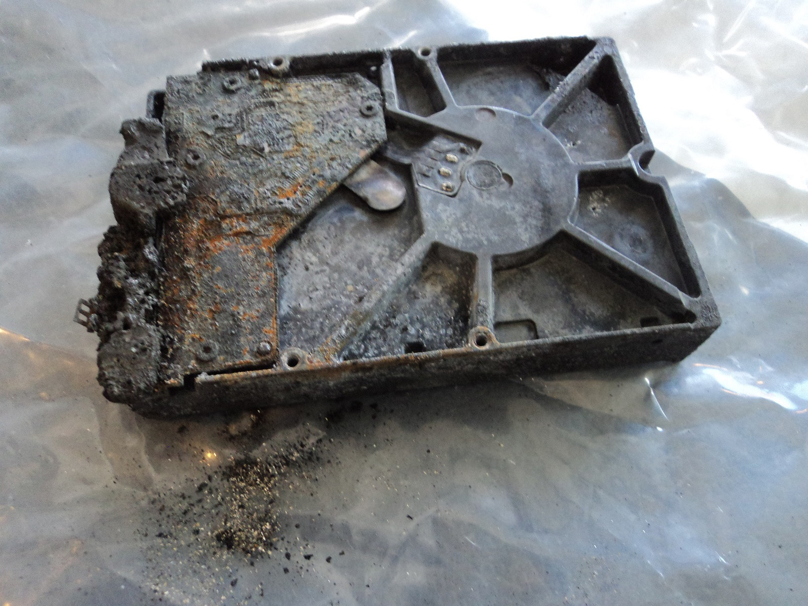
Hardware-Level Hard Drive Repair for All Brands by Seattle Data Recovery
At Seattle Data Recovery, we distinguish between basic data recovery and true hardware-level hard drive repair. When a storage device experiences a mechanical or electronic failure, running recovery software is completely useless—and highly dangerous. The drive must first be physically repaired inside a controlled environment so that it can stabilize long enough to safely extract its data.
Our dedicated laboratory is fully equipped with advanced micro-soldering stations, proprietary firmware terminal tools, and an ISO-certified cleanroom environment. This advanced infrastructure allows our engineers to perform component-level diagnostics and physical restoration across all major hard drive manufacturing brands.
Universal Failure Tiers & Brand-Specific Engineering Protocols
While all hard drives utilize magnetic platters to store data, individual manufacturers rely on wildly different firmware logic, mechanical tolerances, and internal architectures.
Our laboratory engineers deploy specific, brand-calibrated repair procedures to target these unique engineering behaviors:
Western Digital (WD): Bypassing Integrated USB & Encryption
- The Hardware Hurdle: Most portable WD drives (like the My Passport series) do not feature a standard SATA connector. Instead, the USB port and a hardware encryption chip are soldered directly to the main Printed Circuit Board (PCB).
- Our Repair Protocol: If the board suffers a short circuit or the USB port breaks, our technicians perform precision micro-soldering. Under magnification, we tap directly into the drive’s core SATA transmission lines on the board, routing them out to our diagnostic hardware while keeping the encryption chip active to prevent data scrambling.
Seagate: Resolving Seized Spindles & Firmware Loops
- The Hardware Hurdle: Seagate drives feature a compact mechanical design that makes them prone to a "seized spindle motor" or stuck heads if dropped. Additionally, their Media Cache architecture can get trapped in a permanent firmware lock loop when it hits corrupted data sectors.
- Our Repair Protocol: For stuck components, the drive is moved to our dust-free cleanroom where engineers use specialized mechanical tools to safely unstick the head assembly or cleanly migrate the platters to a matching donor chassis. For firmware loops, we link directly to the drive’s system terminal to patch its internal code via RAM commands.
Toshiba: Clearing G-Sensor Lockouts
- The Hardware Hurdle: Toshiba external lines (Canvio series) feature built-in hardware accelerometers (G-Sensors) designed to instantly lock the drive if motion is detected. A sudden drop can trap the drive in a defensive, non-responsive firmware loop.
- Our Repair Protocol: Much like WD, modern Toshiba portable drives utilize integrated USB boards. We convert the native board to a raw SATA path, allowing us to transmit low-level commands that clear out the persistent error logs trapped in the drive’s system memory, stabilizing the controller for data mirroring.
HGST / SanDisk Professional: Enterprise Multi-Platter Alignment
- The Hardware Hurdle: HGST and G-Technology drives spin at higher RPMs (7200 RPM) and often feature tight, multi-platter stacks. They use highly unique NVRAM chips on their PCBs containing custom adaptive alignment data for that specific drive's internal read/write heads.
- Our Repair Protocol: If the PCB fails due to power surges, a simple board swap will fail. Our technicians desolder the original microscopic NVRAM chip and cleanly transplant it onto a perfectly matched donor PCB. Mechanical repairs are performed with absolute precision to maintain the alignment of the multi-platter stack.
The Seattle Data Recovery Hardware Repair Process
Every physically damaged hard drive checked into our lab goes through a strict, controlled restoration pipeline:
- The Cleanroom Inquest: If a drive is clicking, grinding, or beeping, it is never powered on in a standard room. It is opened strictly inside an ISO 5 Cleanroom environment where airborne particles are filtered down to microscopic levels. This prevents dust from landing on the platters and permanently scratching away data.
- Donor Part Matching: Physical part replacements require an incredibly precise match. We maintain an extensive inventory of donor drives, matching not just the model number, but also manufacturing dates, site codes, and internal pre-amplifier revisions.
- Forensic Cloned Imaging: Repaired hard drives are highly unstable and are never meant to be returned to normal use. Once the drive spins up smoothly, it is immediately attached to a hardware imager to create a bit-for-bit digital clone. We extract your data safely from this healthy clone.
Emergency Guidelines: Protect Your Media from Permanent Loss
If your external or internal hard drive exhibits signs of physical failure, your very next action is critical to the survival of your files:
- Disconnect Power Immediately: If the drive is making unusual sounds (clicking, beeping, buzzing), pull the plug. Keeping it powered on can cause a broken read head to physically dig into the spinning platter, shredding your data into unrecoverable dust.
- Say No to DIY Software: File recovery programs are designed for healthy drives with deleted files. Forcing software to scan a drive with a physical head or firmware failure will rapidly overheat and permanently destroy the unit.
- Do Not Open the Drive Casing: Cracking open a hard drive cover outside of a certified cleanroom immediately ruins the drive's internal environment, exposing the platters to millions of microscopic airborne contaminants.
- Details
- Written by: Seattle Data Recovery
- Category: Platters
Objective: To remove dust, fingerprints, smoke particles, and debris from the magnetic surfaces after a head crash or enclosure breach.
Overview
When a hard drive is compromised, microscopic particles settle on the platters. At operational speeds, a single particle of dust acts like a boulder, causing the read/write head to collide with the platter. Decontamination physically removes these contaminants without stripping the ultra-thin magnetic lubricant layer.
Operational Steps
- Extraction: Mount the drive securely in a cleanroom workstation. Remove the top cover using specialized torque-limiting drivers.
- Inspection: Use a high-intensity, monochromatic inspection light at an oblique angle to locate dust, film residues, or fingerprints.
- Solvent Application: Use ultra-pure, electronics-grade isopropyl alcohol (99.9% IPA) or specialized fluorinated solvents.
- Wiping Procedure: Saturate a lint-free, cleanroom-grade polyester swab. Wipe the platter surface using continuous, gentle radial strokes (from the inner hub to the outer edge). Never wipe in a circular motion, as this can track debris across data sectors.
- Drying: Use a clean, pressurized stream of filtered, ionized nitrogen gas to blow away remaining solvents and eliminate static charges that attract dust.
Common Risks & Failures
- Chemical Stripping: Over-saturation or using the wrong solvent can dissolve the protective carbon overcoat of the platter.
- Micro-Scratching: Reusing a contaminated swab can drag a trapped particle across the disc, permanently destroying data sectors.
- Details
- Written by: Seattle Data Recovery
- Category: Data and Power Connectors
Objective: To rebuild a cracked or shattered plastic connector housing and realign bent interface pins to allow temporary, safe insertion of data and power cables.
Overview
The L-shaped plastic shell surrounding SATA data and power pins is notoriously brittle. If a data cable is yanked at an angle, the plastic guide wall often snaps off, leaving raw copper contact pins exposed and floating freely. Without the plastic housing to enforce correct spacing and alignment, plugging a cable in will bend or bridge the pins, causing a severe electrical short circuit that can instantly destroy the drive's main MCU or the computer's power supply.
Operational Steps
- Mechanical Isolation: Unscrew the PCB from the hard drive chassis using precision Torx drivers. Place the bare board on a grounded, ESD-safe cleanroom mat.
- Micro-Pin Realignment: Under a high-magnification stereomicroscope, use ultra-fine titanium tweezers to gently bend any collapsed or twisted copper pins back into perfectly parallel alignment.
- Donor Housing Salvage: Take a OEM PCB of the same connector form factor. Using a hot-air rework station set to 280°C to 300°C with a wide nozzle, gently heat the underside of the OEM connector until the plastic housing can be separated from its structural pins (or use a precision blade to cleanly slice away the plastic guide wall).
- Epoxy Bonding: Carefully slide the salvaged plastic guide channel over the patient pins. Apply a microscopic droplet of structural, non-conductive, fast-curing cleanroom-safe epoxy or UV-curable acrylic resin along the fractured seam.
- Curing and Cleansing: Cure the resin using a focused UV light source. Once hardened, clean any residue off the copper contact pads using a lint-free swab saturated with 99.9% electronic-grade isopropyl alcohol (IPA) to ensure pristine conductivity.
Common Risks & Failures
- Solder Joint Fracturing: Bending a severely warped pin back into place can introduce metal fatigue, causing the pin to snap or fracturing its structural surface-mount solder pad on the PCB.
- Adhesive Contamination: If any epoxy smears onto the top face of the copper contact pins, it will act as an electrical insulator, blocking the SATA cable from making an electrical connection.
- Details
- Written by: Seattle Data Recovery
- Category: Spindle Motor
Objective: To isolate and repair electrical short circuits or open phases within the internal copper windings of the spindle motor stator.
Overview
The spindle motor is a brushless DC motor (BLDC) consisting of permanent magnets attached to the spinning hub (rotor) and a series of stationary copper wire coils (stator). The external PCB sends alternating three-phase electrical pulses to these coils to spin the drive. If a power surge occurs or the motor freezes, the excessive current can melt the microscopic enamel insulation covering the copper wires. This results in a shorted phase or a burned-out coil coil open circuit, which prevents the drive from starting up or maintaining a constant RPM.
Operational Steps
- Phase Resistance Testing: Use a digital multimeter or a data recovery hardware console (like a PC-3000) to measure the resistance across the three motor contact pins on the underside of the HDA (Hard Drive Assembly). Healthy phases usually show balanced, uniform resistance (typically under 5 to 10 ohms depending on the model). A reading of zero indicates a short, while an infinite reading indicates an open circuit.
- Exposing the Stator: Safely extract the platter stack using a multi-platter exchange tool to uncover the motor assembly entirely.
- Micro-soldering Repair: If the open circuit or short is located right at the flexible printed circuit (FPC) termination ribbon pad where the external pins connect to the internal coils, use an ultra-fine soldering tip under a microscope to bridge the broken trace using 0.02mm enameled copper jumper wire.
- Insulation Patching: For minor enamel scrapes, apply a micro-dot of fast-curing UV dielectric resin over the exposed wire strand to prevent it from short-circuiting against the aluminum drive chassis.
- Phase Balance Verification: Re-test the pins with a multimeter to ensure all three phases match exactly in resistance before reinstalling the platter media.
Common Risks & Failures
- Total Phase Imbalance: If a repair changes the electrical resistance of one phase relative to the other two, the motor will suffer from severe rotational jitter. The drive's internal firmware will detect this inconsistent velocity and instantly abort the spin-up sequence for safety.
- Overheating: A compromised stator coil generates far more ambient heat than normal, risking thermal degradation of the adjacent platter lubricant.
- Details
- Written by: Seattle Data Recovery
- Category: Actuator Arm & Voice Coil Actuator
Objective: To safely remove the ultra-powerful top and bottom actuator magnets without damaging the fragile Head Stack Assembly (HSA) and to clear any magnetic debris from the voice coil track.
Overview
The voice coil actuator relies on incredibly strong rare-earth neodymium magnets to create a precise magnetic field. When a hard drive suffers a severe physical impact, these magnets can crack, shatter, or scrape against the voice coil, generating microscopic, highly magnetic shards. Because these magnets exert immense physical pull, removing them requires specialized technique to prevent the magnet from snapping down and crushing the adjacent actuator arm or read/write heads.
Operational Steps
- Stabilize the HSA: Prior to removing the magnets, ensure the read/write heads are locked on their parking ramp or secured with a head comb. This prevents any sudden magnetic shifts from rattling the heads against the platters.
- Apply Vertical Leverage: Use non-magnetic (titanium or heavy-duty plastic) prying tools. Insert the tool beneath the top magnet assembly bracket. Slowly lift vertically, counteracting the strong downward magnetic pull.
- Slide Extraction: Once a gap is established, slide the magnet assembly backward away from the platters. Never lift it directly over the platters, as any accidental drop will catastrophically shatter the media.
- Debris Sweeping: Use a specialized high-tack cleanroom polymer roller or an ESD-safe micro-vacuum to extract microscopic metallic shards trapped in the bottom magnet tray. Standard wipes cannot pull particles away from a strong magnetic field.
- Magnetic Field Verification: Inspect the voice coil gap under a microscope to ensure no sub-micron magnetic fragments remain to cause friction.
Common Risks & Failures
- The "Snap" Effect: If a technician loses their grip on a neodymium magnet, it will violently snap back onto the bottom bracket. This impact can pinch and slice the flexible printed circuit (FPC), bend the actuator arm, or shatter the brittle platter media underneath.
- Latent Contamination: Skipping the microscopic debris sweep leaves tiny metal shards in the track. Upon drive spin-up, the voice coil will drag against these particles, causing immediate tracking errors (Servo track alignment faults).
- Details
- Written by: Seattle Data Recovery
- Category: Actuator Arm & Voice Coil Actuator
Objective: To resolve axis binding or bearing fluid leakage within the central spindle pivot of the actuator arm.
Overview
The entire actuator assembly rotates on a central precision ball-bearing pivot. Over time, the specialized lubricant inside these micro-bearings can dry out, oxidize, or freeze due to physical shock (shattered bearing balls). This creates a condition where the actuator cannot move rapidly enough to track data sectors, throwing continuous "Seek Errors" or locking up completely.
Operational Steps
- Isolate the Axis: Extract the entire HSA from the drive chassis following cleanroom safety protocols (combing the heads first).
- Remove Axis Retainer: Unbolt the central pivot screw or retaining circlip from the bottom and top of the drive chassis using high-precision drivers.
- Pressing the Bearing: Place the actuator assembly into a miniature, calibrated cleanroom hydraulic or mechanical press tool. Gently press the old bearing cartridge vertically out of the aluminum or magnesium arm housing.
- Bore Inspection: Inspect the internal bore of the actuator arm under a microscope to ensure it was not gouged or ovalized during the press extraction.
- Seating the New Bearing: Insert a pristine, lubricated OEM bearing cartridge into the press jig. Press it uniformly into the actuator arm until it is perfectly flush.
- Frictionless Spin Test: Hold the bearing core and spin the actuator arm; it must rotate smoothly without any graininess, clicking, or vertical play.
Common Risks & Failures
- Structural Deformation (Ovalization): If the bearing cartridge is pressed out at even a slight angle, the soft metal bore of the actuator arm will stretch and become ovalized. A replacement bearing will sit loosely in an ovalized bore, causing head wobble that makes data recovery impossible.
- Contaminant Introduction: If microscopic skin flakes or cleanroom fibers touch the exposed bearing race during transfer, the bearing will immediately catch and jam when subjected to the high-speed movements of data retrieval.
Subcategories
Platters
- What it is: Flat, circular metal or glass discs coated in a magnetic material that physically store all digital data.
- Common failures: Head crashes (where read/write heads scratch or gouge the magnetic surface), bad sectors (unreadable data blocks), and physical warping from severe heat or drops.
Read/Write Heads
- What it is: Tiny sensors mounted on the tip of the actuator arm that float a microscopic distance above the spinning platters to read and write data.
- Common failures: Head crash (contact with platters), head stiction (heads getting permanently glued or stuck to the platter surface), and actuator/head degradation causing clicking or beeping noises.
Actuator Arm & Voice Coil Actuator
- What it is: A mechanical arm that sweeps the read/write heads rapidly and precisely across the surface of the platters, controlled by a magnet and coil assembly.
- Common failures: Failed actuator motor/assembly, mechanical binding, or inability to track and position the heads accurately.
Spindle Motor
- What it is: The motor located beneath the platters that spins them at high speeds (typically 5,400 to 7,200 RPM).
- Common failures: Seized motor (failure to spin up, often making a faint ticking, beeping, or humming sound) or worn bearings that cause grinding noises and wobbling platters.
Printed Circuit Board (PCB / Controller Board)
- What it is: The external green or black circuit board attached to the bottom of the drive that translates signals, controls the motor, and manages data flow.
- Common failures: Electrical short circuits or component burn-out caused by power surges, static discharge, or a faulty power supply, which can render the drive completely dead ("no power/no spin").
Firmware (System Area)
- What it is: Low-level internal software stored on a reserved portion of the platters and PCB that boots the drive and tells the heads how to operate.
- Common failures: Firmware corruption from bugs, improper updates, or unexpected power loss, which causes the drive to spin up but fail to be recognized by the computer.
Cache Memory (DRAM)
- What it is: A small, high-speed volatile memory chip on the PCB that temporarily holds frequently accessed data.
- Common failures: Data corruption or chip failure due to voltage spikes or overheating.
Air/Breather Filter
- What it is: A tiny internal filter that equalizes internal air pressure with the outside while trapping microscopic dust particles.
- Common failures: Clogging or seal failure that lets dust and moisture inside, leading to platter contamination and corrosion.
Data and Power Connectors
- What it is: The physical pins/ports that plug the drive into the computer's motherboard and power supply.
- Common failures: Bent or broken pins, loose cable connections, or corroded contact pads.