
Call 1 (425) 406-1174 to start a Data Recovery!
Hard Drive Repairs
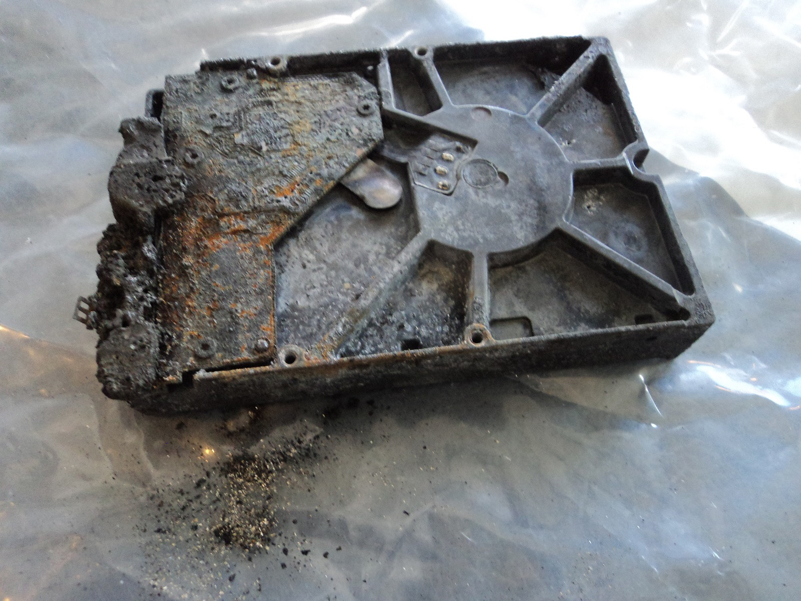
Hardware-Level Hard Drive Repair for All Brands by Seattle Data Recovery
At Seattle Data Recovery, we distinguish between basic data recovery and true hardware-level hard drive repair. When a storage device experiences a mechanical or electronic failure, running recovery software is completely useless—and highly dangerous. The drive must first be physically repaired inside a controlled environment so that it can stabilize long enough to safely extract its data.
Our dedicated laboratory is fully equipped with advanced micro-soldering stations, proprietary firmware terminal tools, and an ISO-certified cleanroom environment. This advanced infrastructure allows our engineers to perform component-level diagnostics and physical restoration across all major hard drive manufacturing brands.
Universal Failure Tiers & Brand-Specific Engineering Protocols
While all hard drives utilize magnetic platters to store data, individual manufacturers rely on wildly different firmware logic, mechanical tolerances, and internal architectures.
Our laboratory engineers deploy specific, brand-calibrated repair procedures to target these unique engineering behaviors:
Western Digital (WD): Bypassing Integrated USB & Encryption
- The Hardware Hurdle: Most portable WD drives (like the My Passport series) do not feature a standard SATA connector. Instead, the USB port and a hardware encryption chip are soldered directly to the main Printed Circuit Board (PCB).
- Our Repair Protocol: If the board suffers a short circuit or the USB port breaks, our technicians perform precision micro-soldering. Under magnification, we tap directly into the drive’s core SATA transmission lines on the board, routing them out to our diagnostic hardware while keeping the encryption chip active to prevent data scrambling.
Seagate: Resolving Seized Spindles & Firmware Loops
- The Hardware Hurdle: Seagate drives feature a compact mechanical design that makes them prone to a "seized spindle motor" or stuck heads if dropped. Additionally, their Media Cache architecture can get trapped in a permanent firmware lock loop when it hits corrupted data sectors.
- Our Repair Protocol: For stuck components, the drive is moved to our dust-free cleanroom where engineers use specialized mechanical tools to safely unstick the head assembly or cleanly migrate the platters to a matching donor chassis. For firmware loops, we link directly to the drive’s system terminal to patch its internal code via RAM commands.
Toshiba: Clearing G-Sensor Lockouts
- The Hardware Hurdle: Toshiba external lines (Canvio series) feature built-in hardware accelerometers (G-Sensors) designed to instantly lock the drive if motion is detected. A sudden drop can trap the drive in a defensive, non-responsive firmware loop.
- Our Repair Protocol: Much like WD, modern Toshiba portable drives utilize integrated USB boards. We convert the native board to a raw SATA path, allowing us to transmit low-level commands that clear out the persistent error logs trapped in the drive’s system memory, stabilizing the controller for data mirroring.
HGST / SanDisk Professional: Enterprise Multi-Platter Alignment
- The Hardware Hurdle: HGST and G-Technology drives spin at higher RPMs (7200 RPM) and often feature tight, multi-platter stacks. They use highly unique NVRAM chips on their PCBs containing custom adaptive alignment data for that specific drive's internal read/write heads.
- Our Repair Protocol: If the PCB fails due to power surges, a simple board swap will fail. Our technicians desolder the original microscopic NVRAM chip and cleanly transplant it onto a perfectly matched donor PCB. Mechanical repairs are performed with absolute precision to maintain the alignment of the multi-platter stack.
The Seattle Data Recovery Hardware Repair Process
Every physically damaged hard drive checked into our lab goes through a strict, controlled restoration pipeline:
- The Cleanroom Inquest: If a drive is clicking, grinding, or beeping, it is never powered on in a standard room. It is opened strictly inside an ISO 5 Cleanroom environment where airborne particles are filtered down to microscopic levels. This prevents dust from landing on the platters and permanently scratching away data.
- Donor Part Matching: Physical part replacements require an incredibly precise match. We maintain an extensive inventory of donor drives, matching not just the model number, but also manufacturing dates, site codes, and internal pre-amplifier revisions.
- Forensic Cloned Imaging: Repaired hard drives are highly unstable and are never meant to be returned to normal use. Once the drive spins up smoothly, it is immediately attached to a hardware imager to create a bit-for-bit digital clone. We extract your data safely from this healthy clone.
Emergency Guidelines: Protect Your Media from Permanent Loss
If your external or internal hard drive exhibits signs of physical failure, your very next action is critical to the survival of your files:
- Disconnect Power Immediately: If the drive is making unusual sounds (clicking, beeping, buzzing), pull the plug. Keeping it powered on can cause a broken read head to physically dig into the spinning platter, shredding your data into unrecoverable dust.
- Say No to DIY Software: File recovery programs are designed for healthy drives with deleted files. Forcing software to scan a drive with a physical head or firmware failure will rapidly overheat and permanently destroy the unit.
- Do Not Open the Drive Casing: Cracking open a hard drive cover outside of a certified cleanroom immediately ruins the drive's internal environment, exposing the platters to millions of microscopic airborne contaminants.
- Details
- Written by: Seattle Data Recovery
- Category: Actuator Arm & Voice Coil Actuator
Objective: To correct structural warping or thermal deformation of the voice coil loop, ensuring unhindered movement within the magnetic gap.
Overview
The voice coil is a copper or aluminum wire loop wrapped around the back of the actuator arm. When current passes through it, it interacts with the permanent magnets to move the arm. Intense overheating, power surges, or mechanical shocks can cause the coil loop to warp, expand, or tilt. This leads to coil binding, where the coil physically rubs against the top or bottom magnet plates, preventing the heads from sweeping smoothly across the platters.
Operational Steps
- Friction Profiling: With the drive powered off and top magnet removed, use an ultra-fine, non-magnetic probe to gently nudge the actuator arm through its full range of motion to locate the exact point of mechanical resistance.
- Micro-Gap Calibration: Re-seat the top magnet and use brass feeler gauges (non-magnetic) to measure the clearance between the coil and the upper/lower magnetic plates. The clearance is typically uniform and microscopic.
- Thermal/Mechanical Reshaping: If the coil frame is slightly warped, technicians use precision cleanroom micro-clamps to gently apply counter-pressure, restoring the flat profile of the coil frame.
- Insulation Repair: If the protective enamel coating on the coil wires has scraped off, apply a microscopic layer of ultra-thin, fast-curing UV dielectric resin to prevent electrical shorting against the magnet chassis.
- Sweep Testing: Manually sweep the arm repeatedly to ensure zero resistance across the entire arc from the inner diameter (ID) to the outer diameter (OD) of the platters.
Common Risks & Failures
- Coil Rupture: The wires making up the voice coil are exceptionally fine. Applying excessive physical force during reshaping can snap an internal wire strand, resulting in an open circuit that kills the actuator completely.
- Resin Over-application: Adding too much dielectric resin adds mass to the back of the actuator arm. This offsets the perfectly balanced counterweight system of the HSA, making it impossible for the drive's servo system to calculate positioning accurately.
- Details
- Written by: Seattle Data Recovery
- Category: Read/Write Heads
Objective: To extract a physically or electrically failed head stack assembly and swap it with a perfectly compatible OEM head stack.
Overview
If a drive's heads are physically broken, or if the preamplifier chip on the actuator arm burns out, the entire Head Stack Assembly (HSA) must be replaced. This is a highly complex physical transplant. The technician must locate a "OEM drive" that matches the patient drive down to exact parameters, including model number, firmware architecture, site code, and head maps.
Operational Steps
- Isolate the Voice Coil: Remove the top neodymium magnet assembly of the voice coil actuator to expose the rear of the actuator arm.
- Apply Head Combs: Insert a specialized, drive-specific head comb into the head stack. The comb slides between the suspension arms, physically separating the upper and lower heads. Heads must never touch each other, as their magnetic elements will destroy one another instantly.
- Unbolt and Extract: Remove the main actuator axis screw and disconnect the flexible printed circuit (FPC) from the internal chassis contacts. Lift the HSA vertically out of the patient chassis using ESD-safe tweezers.
- Donor Preparation: Perform the exact same extraction process on the compatible OEM drive, ensuring the OEM heads are immediately combed upon removal.
- Transplant and Torque: Lower the OEM HSA into the patient drive chassis. Re-secure the actuator axis screw using a calibrated torque screwdriver.
- FPC Connection: Reconnect and seal the flexible circuit contacts to the drive's external PCB connector. Remove the head combs only after the heads are safely positioned near the parking ramp.
Common Risks & Failures
- Head Clashing: Skipping the use of a head comb or using a generic comb allows the heads to snap together. The impact instantly shatters the microscopic giant magnetoresistive (GMR) or tunneling magnetoresistive (TMR) elements.
- Preamplifier Shock: The preamplifier chip on the HSA is incredibly sensitive to static. A single microscopic electrostatic discharge (ESD) will fry the OEM head before it is even tested.
- Details
- Written by: Seattle Data Recovery
- Category: Spindle Motor
Objective: To break the locked state of a seized Fluid Dynamic Bearing (FDB) to allow the motor to spin long enough for data extraction.
Overview
Modern hard drives use Fluid Dynamic Bearings (FDB) instead of traditional ball bearings. FDBs rely on a microscopic layer of viscous oil to keep the spindle shaft suspended. If a drive sits unused for years, undergoes a physical drop, or experiences severe overheating, this oil can oxidize, dry up, or become contaminated with microscopic debris. This locks the shaft in place (a seized spindle). When powered, the drive cannot spin and usually emits a faint, repeating ticking or buzzing sound as the circuit board tries to kick-start the frozen motor.
Operational Steps
- Isolate the Component: Strip the hard drive down to its bare chassis. Remove the external printed circuit board (PCB) and extract the head stack assembly (HSA) using specialized head combs to prevent any platter contact.
- Apply Rotational Mechanical Force: Insert a proprietary, multi-pin spindle-turning tool into the top hub of the spindle. Attempt to apply progressive, manual counter-rotational force. If the seizure is minor, the mechanical shock will break the chemical or debris bond.
- Controlled Thermal Shock: If manual force fails, utilize an ESD-safe thermal chamber. Cool the entire chassis down to -10°C to -18°C for approximately 45 minutes to cause the metal casing and the fluid sleeve to contract at slightly different rates.
- Immediate Mechanical Manipulation: Remove the drive from the chamber and immediately apply the spindle-turning tool. The microscopic gap variance created by the thermal contraction often allows the shaft to break free.
- Viscosity Restoration: If successful, manually spin the platter stack continuously for several minutes inside the cleanroom workspace to evenly redistribute any remaining fluid before reassembling the drive.
Common Risks & Failures
- Platter Warping: Applying excessive mechanical torque to a frozen spindle hub can distort the center of the metal platters, causing permanent track registration failure.
- Fluid Evaporation/Migration: Breaking a seizure via thermal or mechanical force often leaves the bearing unstable. The motor may run for only a few minutes before friction causes a catastrophic thermal lockup, meaning data imaging must begin immediately.
- Details
- Written by: Seattle Data Recovery
- Category: Cache Memory (DRAM)
Objective: To bypass a defective or unstable DRAM chip in real-time using hardware emulation to capture data before the cache drops offline.
Overview
The DRAM chip acts as a high-speed buffer, caching data blocks before they are committed to the platters or sent to the host computer. If a DRAM chip suffers from thermal degradation or internal bit-flips, it will trigger sporadic hanging, drop connection mid-stream, or cause the drive to fail initialization. In critical recovery scenarios where the original PCB must remain active, a hardware emulation console (such as an ACELab PC-3000 system) can be used to stabilize the volatile buffer environment. [1, 2, 3]
Operational Steps
- Isolate and Intercept: Mount the hard drive onto a cleanroom diagnostics bench. Connect the drive to a data recovery hardware suite via the physical SATA link and a serial-TTL terminal link. [1]
- Safe-Mode Initialization: Power on the drive in a safe-mode state to prevent the drive's microcode from loading full cache allocations into the hardware DRAM.
- RAM Mirroring Configuration: Through the hardware utility terminal, issue Vendor Specific Commands (VSCs) to reallocate the internal processor's data streaming pathway.
- Buffer Redirection: Configure the data recovery software to bypass the physical onboard DRAM chip for sector-by-sector caching. Instruct the utility to stream data directly from the drive's read-channel chip straight into the hardware console's internal, virtualized RAM buffer.
- Targeted Sub-Imaging: Immediately begin low-speed, sector-by-sector imaging. Skip large file caching blocks entirely to minimize the electrical load on the failing onboard DRAM module. [1, 2]
Common Risks & Failures
- Firmware Assertions: If the drive's firmware detects that the hardware cache is completely unresponsive, it may trigger an internal fatal exception error, locking the drive into a persistent "Busy" state that requires a force-reboot.
- Thermal Avalanche: An unstable DRAM chip often overheats rapidly. If the extraction process is run too quickly, the chip can experience complete thermal failure, which can short out the adjacent main Microcontroller Unit (MCU).
- Details
- Written by: Seattle Data Recovery
- Category: Platters
Objective: To stabilize a platter that has suffered severe physical gouging from a read/write head, preventing further destruction during data recovery.
Overview
A head crash occurs when the read/write head physically plows into the spinning platter, shaving off the magnetic coating. This creates a ring of destruction called a concentric scratch and generates highly abrasive metallic dust inside the drive. While scraped data cannot be recovered, the surrounding areas can often be saved if the drive is stabilized.
Operational Steps
- Debris Evacuation: Vacuum the internal drive chassis using a specialized ESD-safe micro-vacuum to remove the metallic dust generated by the crash.
- Microscopic Mapping: Place the platters under a high-magnification optical microscope to map out the exact radial boundaries of the physical gouges.
- Burnishing (Edge Smoothing): If a scratch has raised sharp metal ridges (burrs) on the platter surface, technicians use specialized micro-abrasive burnishing tape to gently smooth down the raised edges. This prevents a replacement head from clipping the burr and crashing instantly.
- Targeted Sector Exclusion: Document the exact physical location of the damage. This mapping data is fed into data recovery hardware (such as an PC-3000) to instruct the drive to skip those damaged zones entirely during the imaging process.
Common Risks & Failures
- Instability: Burnishing is a high-risk operation. If the platter surface becomes uneven, the aerodynamic "air bearing" that lifts the heads collapses, causing an immediate secondary head crash.
- Rapid Head Blindness: If even a tiny trace of metallic dust remains on the platter, it will instantly destroy the replacement head stack upon spin-up.
Subcategories
Platters
- What it is: Flat, circular metal or glass discs coated in a magnetic material that physically store all digital data.
- Common failures: Head crashes (where read/write heads scratch or gouge the magnetic surface), bad sectors (unreadable data blocks), and physical warping from severe heat or drops.
Read/Write Heads
- What it is: Tiny sensors mounted on the tip of the actuator arm that float a microscopic distance above the spinning platters to read and write data.
- Common failures: Head crash (contact with platters), head stiction (heads getting permanently glued or stuck to the platter surface), and actuator/head degradation causing clicking or beeping noises.
Actuator Arm & Voice Coil Actuator
- What it is: A mechanical arm that sweeps the read/write heads rapidly and precisely across the surface of the platters, controlled by a magnet and coil assembly.
- Common failures: Failed actuator motor/assembly, mechanical binding, or inability to track and position the heads accurately.
Spindle Motor
- What it is: The motor located beneath the platters that spins them at high speeds (typically 5,400 to 7,200 RPM).
- Common failures: Seized motor (failure to spin up, often making a faint ticking, beeping, or humming sound) or worn bearings that cause grinding noises and wobbling platters.
Printed Circuit Board (PCB / Controller Board)
- What it is: The external green or black circuit board attached to the bottom of the drive that translates signals, controls the motor, and manages data flow.
- Common failures: Electrical short circuits or component burn-out caused by power surges, static discharge, or a faulty power supply, which can render the drive completely dead ("no power/no spin").
Firmware (System Area)
- What it is: Low-level internal software stored on a reserved portion of the platters and PCB that boots the drive and tells the heads how to operate.
- Common failures: Firmware corruption from bugs, improper updates, or unexpected power loss, which causes the drive to spin up but fail to be recognized by the computer.
Cache Memory (DRAM)
- What it is: A small, high-speed volatile memory chip on the PCB that temporarily holds frequently accessed data.
- Common failures: Data corruption or chip failure due to voltage spikes or overheating.
Air/Breather Filter
- What it is: A tiny internal filter that equalizes internal air pressure with the outside while trapping microscopic dust particles.
- Common failures: Clogging or seal failure that lets dust and moisture inside, leading to platter contamination and corrosion.
Data and Power Connectors
- What it is: The physical pins/ports that plug the drive into the computer's motherboard and power supply.
- Common failures: Bent or broken pins, loose cable connections, or corroded contact pads.